Special alloy fasteners
Stud bolts &
threaded rods
Nickel alloys, duplex steels and titanium for flange connections, equipment covers and assemblies.
- Diameter
- M4–M100 / 1/4″–4″
- Threads
- Metric · UNC · UNF · 8UN · UNJ
- Stud forms
- Full thread · Double-ended · Tap-end
Find your material.
Search the grade or UNS on your specification.
Product and thread standards
Check the product geometry, thread form and flange assembly requirements against your drawing.
Metric
- DIN 976-1
- Metric studs threaded along their full length, for assemblies with nuts at both ends.
- ASME B1.13M
- Metric M-profile threads: diameter, pitch and tolerance requirements for mating parts.
Metric threads
Inch
- ASME B18.31.2
- Inch dimensions for continuous-thread, double-end and flange bolting studs.
- ASME B1.1-2024
- Unified inch thread profiles, series and fit classes, including UNJ thread forms.
UNC · UNF · 8UN · UNJ
Flange assembly references
ASME B16.5
Pipe flanges and flanged fittings, NPS ½–24. Includes flange bolting requirements and dimensional recommendations.
ASME B16.47
Large-diameter steel flanges, NPS 26–60. Flange series and pressure class identify the connection geometry.
For flange bolting, include the flange standard, size and class with your stud-and-nut list.
Thread inspection
Sampled GO / NO-GO gauging to the specified thread class and drawing tolerances.
Thread manufacturing methods +
Rolled threads
Threads formed by displacement of material. The alloy condition, tooling and thread profile define the rolling route.
Cut threads
Threads machined into the stock, including special pitches and drawing-specific end configurations.
Special geometry & surface finish +
Tap-end engagement, reduced shanks, unequal thread lengths and special end details can be included in your drawing. Add any specified PTFE/Xylan coating or passivation requirement to the enquiry.
Three stud configurations.
Continuous thread
Threaded along the body, with nuts at both ends of the connection.
Double-ended
Two threaded ends separated by a plain shank. End lengths can differ.
Tap-end pattern
One end enters a tapped component; the other accepts a nut. Specify the engagement end.
Dimensions & thread specification +
| Feature | Full thread | Double / tap end |
|---|---|---|
| d | Nominal thread diameter | |
| L | Overall end-to-end length in the diagram above | |
| b₁ / b₂ | Continuous thread | Threaded length at each end |
| Mating nut | Same nominal diameter, pitch and compatible thread form | |
Quality & documentation
EN 10204 3.1 MTC, heat traceability and mechanical test results with each shipment.
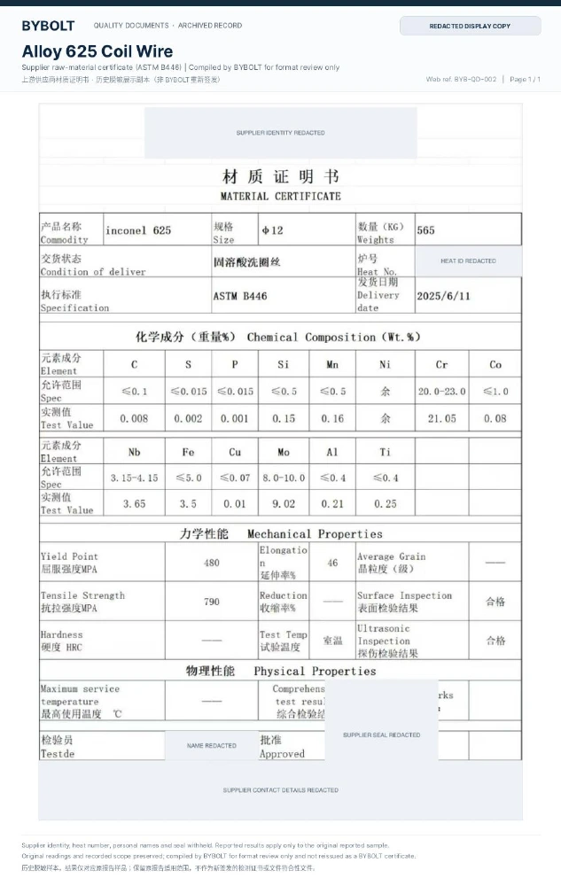
Material certificate
Inconel 625 · historical coil-wire sample

Laboratory report
Inconel 718 · chemistry, tensile & hardness
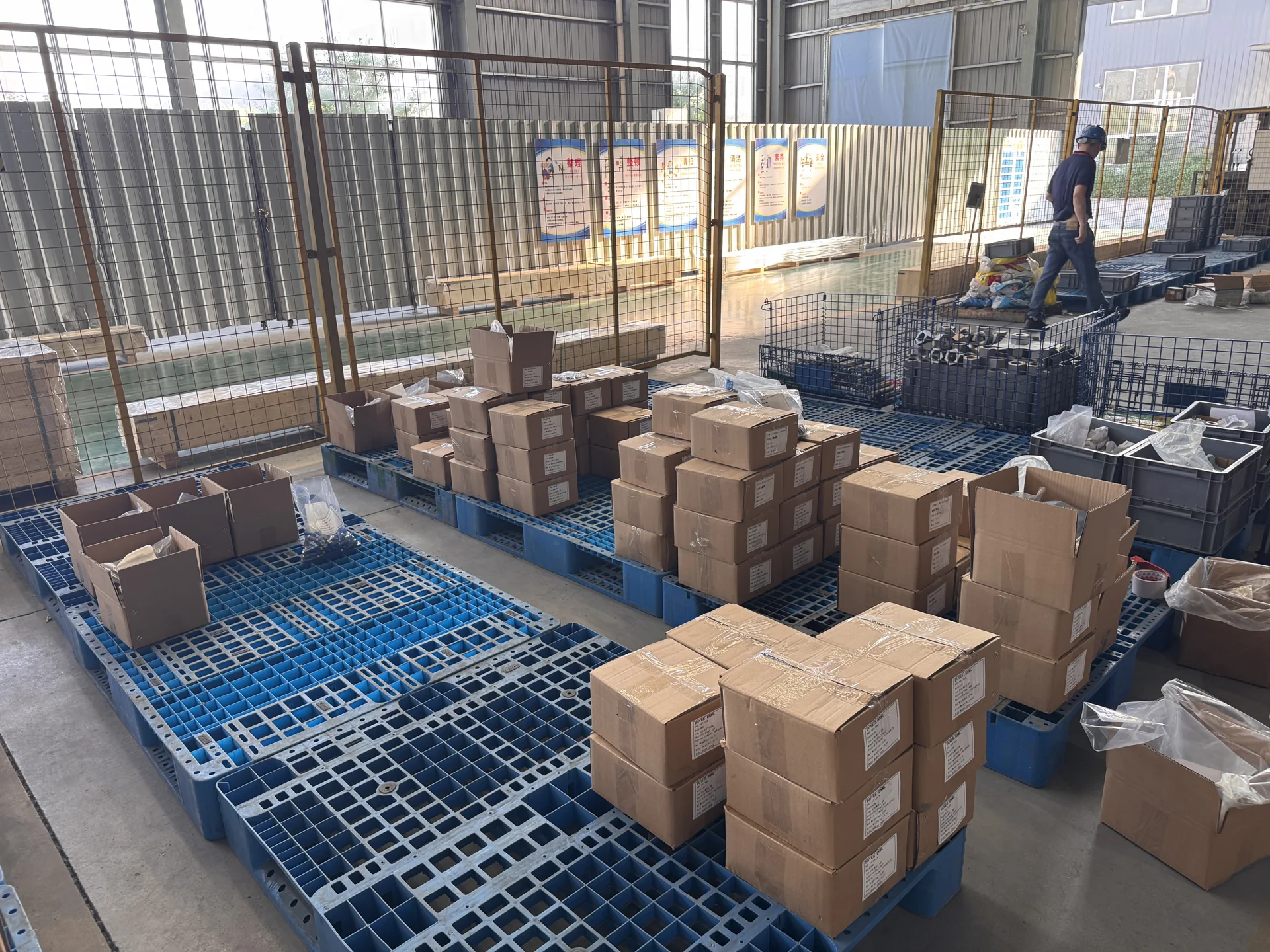
Identified packing
Heat and batch records linked to the shipment
Additional inspection requirements +
PMI, third-party inspection and witness testing can be included in the order. Specify any UT/PT procedure, acceptance criteria, hardness limits or heat-treatment records required by your project.
Industries we serve.



Complete the connection.
One drawing. One coordinated quotation.
Studs, nuts and washers can be quoted together by assembly or BOM line.
Photo credits
- Oil and gas — BYBOLT · User-supplied Google Flow image · . Web compression and display crop.
- Offshore and marine — BYBOLT · User-supplied Google Flow image · . Web compression and display crop.
- Chemical processing — BYBOLT · User-supplied Google Flow image · . Web compression and display crop.