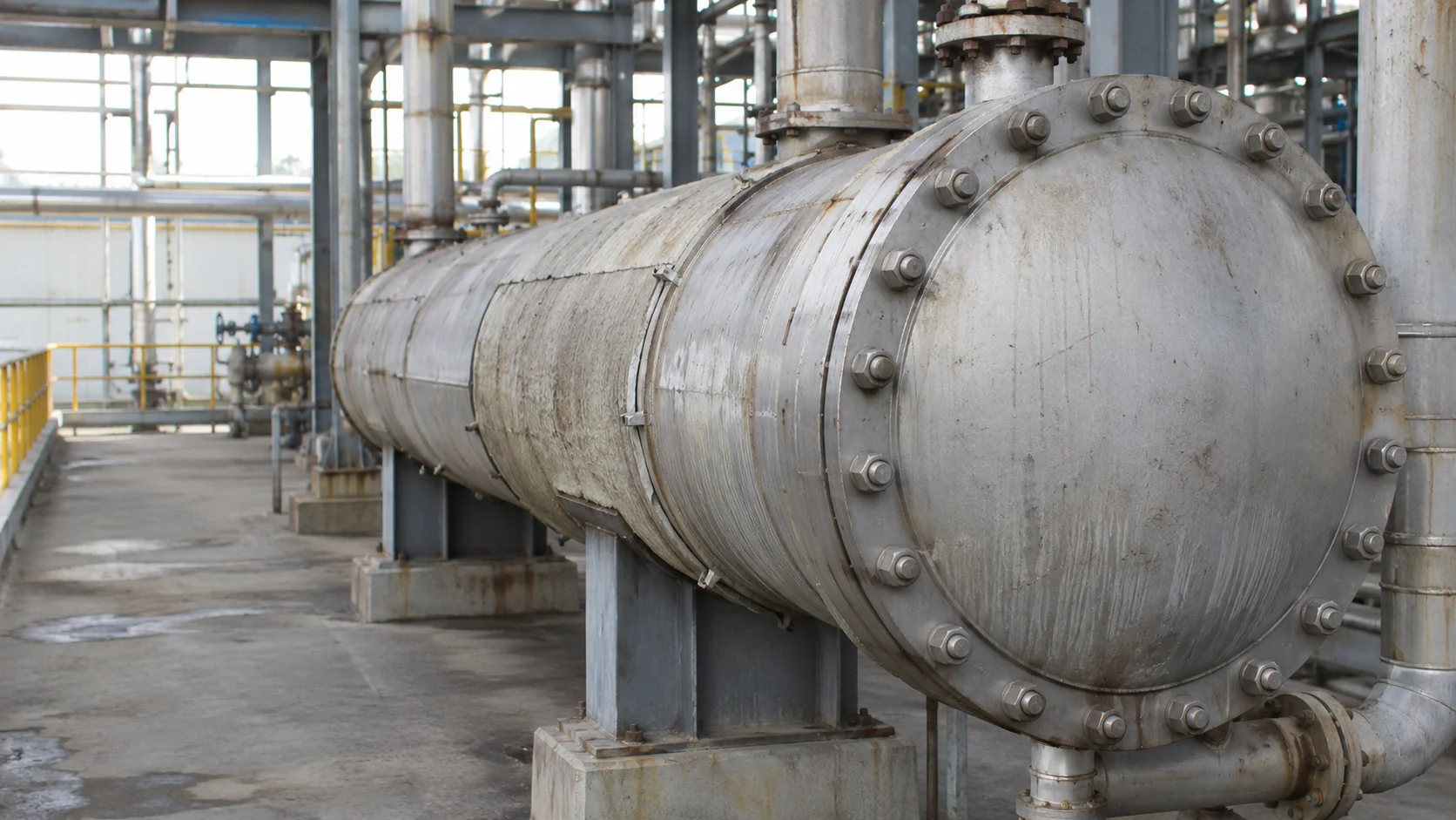
This article is about ordering a head stud set for all three exposures, not just the headline medium. The main fluid, the cleaning fluid, and the liquid that stays behind after draining all have to be stated together. A stud that survives the first two can still pit in the third.
The head, the gasket stack, and the stud length belong in the same enquiry. A set ordered by grade alone leaves the gasket, the usable thread, and the tool space to chance, and a head opened for cleaning exposes each of those gaps in turn.
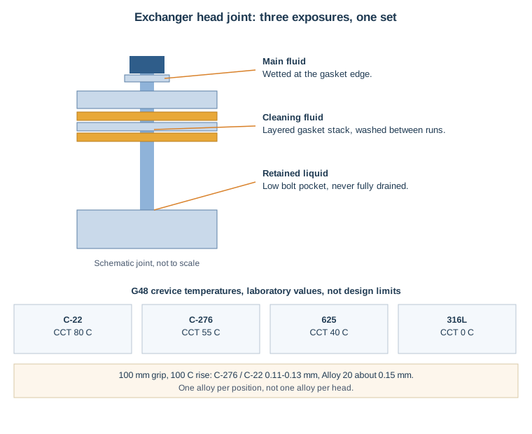
Figure: Exchanger head joint — main fluid, cleaning fluid, and retained liquid in a low bolt pocket; G48 crevice temperatures are laboratory values.
01 Three exposures, not one medium
A head joint sees three liquids, not one. The process fluid runs on the tube side or the shell side, the cleaning fluid runs during a wash, and a third liquid stays behind in the head, in a bolt pocket, or under a washer after draining. Cleaning chemistry is a separate corrosion duty from the main fluid: a cleaning agent that is safe for the tube bundle can still attack a stud thread root, a washer face, or a crevice under a nut, where liquid sits still after the wash.
Retained liquid is the quietest of the three. A head that is drained but not flushed leaves a low pocket, a bolt hole, or a gasket groove wet with the last fluid, often concentrated by evaporation during a hot shutdown. That pocket then works as a crevice, holding stagnant, oxygen-starved liquid whose chemistry turns aggressive while the open surface still looks sound. Laboratory crevice data show how far apart alloys sit in one aggressive solution. In acidified 6% ferric chloride under ASTM G48, Haynes International's HASTELLOY C-276 alloy page gives a critical crevice temperature of 55°C for C-276, against 40°C for 625 and 0°C for 316L, while Haynes International's HASTELLOY C-22 alloy page gives 80°C for C-22. Those are laboratory test values in one solution, not service limits, and they set the order rule: check the alloy against the liquid that sits in the crevice, not the liquid that flows past the head.
- Identify the three liquids per head: main fluid, cleaning fluid with its concentration and temperature, and the liquid left behind after draining.
- Map the low pockets: head pockets, bolt holes, gasket grooves, and the space under each washer, where liquid can sit still between openings.
- Record the drain and flush practice: what is drained, what is flushed, and what is left to evaporate during a hot shutdown.
02 Gasket stacks decide stud length, and thermal cycling decides preload
A head stud set must span the head, the gasket stack, the washer, and the nut, with enough thread left for full nut engagement. A gasket stack is not one gasket: it can be a single gasket, a gasket with a spacer, or a stacked arrangement where each layer adds thickness and compressibility. Each layer changes the grip length, which is the length of stud that must span the joint before the nut engages, and each layer changes how much the joint relaxes when temperature changes.
Thermal cycling drops seating force. As a head heats and cools, the head, the tube sheet, the bolts, and the gasket expand and contract at different rates, and the gasket seating force can fall even though no nut has turned. Bolt Science's stress relaxation technical page describes that loss from the bolt side of the joint: preload falls with no rotation of the fastener. State the operating temperature range, the shutdown temperature, the gasket type and stack, and whether re-tightening at operating temperature is part of the procedure. A stud length that fits the cold assembly but leaves short usable thread after the gasket stack is compressed will not seat the head evenly at temperature.
- Dimension the stack layer by layer: head thickness, tube-sheet or flange thickness, each gasket layer, washer thickness, nut height, and the required thread engagement at each end.
- State the temperature range and the re-tightening procedure: operating range, shutdown temperature, and whether the procedure calls for re-tightening once operating conditions are reached.
- Fix the tightening pattern and method: a multi-pass diametrically staggered pattern, with torque, torque-angle, or tensioning named on the order. Torque-angle means tightening to a stated torque and then turning the nut a further stated angle, which gives a more repeatable stretch than torque alone where friction varies.
03 The candidate alloys, and where each one stops
No single alloy answers a chemical exchanger head. The material follows the actual medium, and the four candidates below are the shortlist to check against the three exposures.
| Candidate | UNS and form | Where it fits a head joint | Boundary to watch |
|---|---|---|---|
| Hastelloy C-276 | UNS N10276, bar to ASTM B574 | Mixed and reducing acids with chloride | Solution-annealed minima 690 MPa tensile, 283 MPa yield under ASTM B574, with a governing-edition hedge; size for annealed yield, not high-strength steel values |
| Hastelloy C-22 | UNS N06022, bar to ASTM B574 | Oxidizing-leaning mixed acid, ferric and cupric chloride | Solution-annealed yield about 283–310 MPa by form and edition; name the specification on the order |
| Alloy 20 | UNS N08020, bar to ASTM B473 | Dilute sulfuric, chloride and HCl inside its qualified envelope | Mid-range hot sulfuric and chloride beyond its envelope; stabilized-annealed minima 551 MPa tensile, 241 MPa yield under ASTM B473, with a governing-edition hedge |
| 316L | UNS S31603 | Mild, dilute, cool service only | Retained cleaning liquid and chloride-bearing mixed acid; laboratory crevice temperature 0°C in the solution above |
Expansion sets a second check. Haynes International's HASTELLOY C-276 alloy page gives a mean coefficient of thermal expansion of 11.2 µm/m·K over 24–100°C, rising to 13.1 µm/m·K over 24–400°C, while Haynes International's HASTELLOY C-22 alloy page gives 12.4 µm/m·K over 24–100°C, rising to 13.1 µm/m·K over 24–400°C. Carpenter Technology's CarTech 20Cb-3 datasheet gives about 14.7 µm/m·K for Alloy 20 over 77–212°F. Over a 100 mm grip and a 100°C rise, that is about 0.11–0.13 mm for C-276 and C-22, against about 0.15 mm for Alloy 20. The difference is small beside a gasket stack, and it still decides whether a hot joint keeps its seating force or gives it away at the washer face.
ASTM B574 and ASTM B473 are bar standards, not finished-stud specifications. The order still has to state finished-stud dimensions for flange bolting per ASME B16.5, a rounded-root thread form such as UNR or UNJ, whether threads are rolled before or after the final anneal, and the matching nut and washer. A bar certificate alone does not prove the finished, threaded stud meets the condition the head was sized on.
04 Define the set: total length, usable thread, and tool space
A head stud fails on length more often than on grade. Give the head thickness, the tube-sheet or flange thickness, the full gasket stack with each layer's thickness, the washer thickness, the nut height, and the required thread engagement at each end, and dimension both ends on the drawing. Total length alone is not enough: a stud that is long enough overall but short on usable thread at the nut end will not seat the gasket evenly, and a stud that is long at the nut end but short in the head thread will pull out of the tapped hole. State whether the head uses through-bolts with nuts on both ends or studs into tapped holes, since the two arrangements need different length definitions and different tool space.
Tool space is a joint dimension, not a workshop convenience. A head bolt circle that leaves no room for a torque wrench, a tensioner, or a socket at one position will be tightened unevenly at that position, and the gasket will leak there first. State the tightening sequence, the tightening method, and the tool for every nut position, and check on the drawing that the tool can actually reach each one. At turnaround, inspect removed studs by position: pitting under the nut and washer, thread-root attack, and any stud that needed cutting to remove.
State the nut alloy, UNS, and condition separately. An unstated nut changes the crevice picture, the galvanic risk, and the galling risk at the joint. Bossard's technical note on galling describes the oxide-breakdown picture for stainless threads, and lubricant stays a stated order item for nickel-alloy threads too. An unstated lubricant, like an unstated nut, leaves the first opening to chance.
Send the head drawing, the gasket stack, the three exposures, and the temperature range to the BYBOLT engineering team for a check before ordering. That check is where a head set is caught with a stud length that seats the gasket on one side and not the other, a nut pairing that changes the crevice picture, or a cleaning chemical that was never checked against the stud alloy.
At receipt, the BYBOLT quality pack should tie each stud set to its heat, its heat-treatment record, and its hardness report for the finished condition. Ask for EN 10204 3.1 certificates, a dimensional report for the actual studs, and a PMI report where the project requires it. The receipt pack must evidence the finished, threaded stud, since the head was sized on that stud, not on the bar it came from.
| What to lock before ordering | Why it changes the joint | Document to ask for |
|---|---|---|
| Main fluid, cleaning fluid, retained liquid | Three exposures, not one medium | Fluid datasheets, cleaning specification, drain and flush practice |
| Gasket stack, washer, and nut height | Decides grip length and usable thread at each end | Drawing with gasket stack and both ends dimensioned |
| Temperature range and re-tightening procedure | Thermal cycling drops gasket seating force | Process datasheet, tightening and re-tightening procedure |
| Through-bolt or tapped-hole arrangement, tool space | Decides length definition and whether every nut can be tightened evenly | Head drawing, tool-space check |
| Nut alloy, UNS, and condition | An unstated nut changes crevice, galvanic, and galling risk | Nut standard and condition on the certificate |
| Set list and records | Mixed sets on a head cannot be audited after a leak | Set list by head position, EN 10204 3.1 certificates, PMI where specified |
05 Ask for a quote with the head, not just the grade
If a chemical exchanger head is being re-specified, or if a head set is being considered to replace a leaking set, send the head with the size. A note like "M24 head stud set for a chemical heat exchanger, mixed acid service with caustic cleaning, cleaning concentration to be confirmed, 150°C stud temperature to be confirmed from the process datasheet, gasket stack to be confirmed from the drawing, 20-bolt set" gives the BYBOLT engineering team enough to check alloy, length, nut pairing, and cleaning exposure before quoting. Even a photo of a removed stud, showing pitting under the nut or washer, helps show whether the last failure started in a crevice, at the washer face, or at the gasket edge.
Send that note with the drawing if you have it, and the team will work through the missing fluid, temperature, or engagement details with you before quoting a small batch or a full set with EN 10204 3.1 traceability.