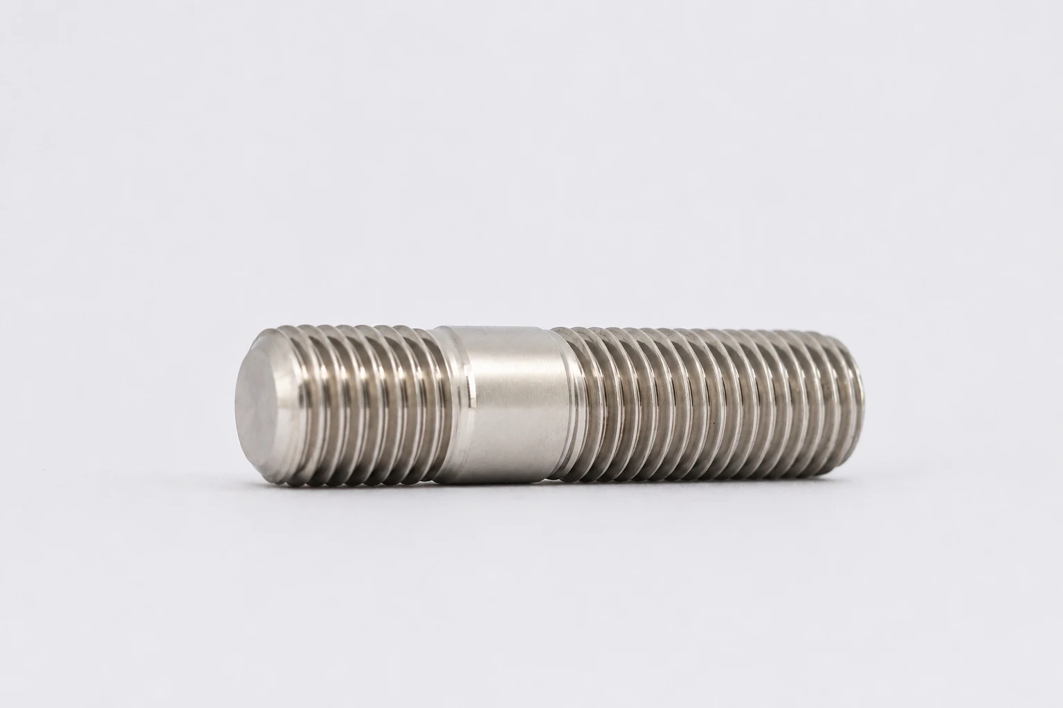
Measure a stud bolt from the two reference points defined on its drawing—not from the word “length” alone. Record the physical end-to-end length separately if the specified length uses thread boundaries or excludes an insertion end. Then identify the thread at each end and the complete-thread region needed by the mating parts.
For an Inconel 718 or A-286 replacement, those measurements establish the shape to be quoted. They do not establish the alloy condition, finished-fastener properties or suitability for the original service. Keep those requirements with the same drawing revision as the dimensions.
This guide is part of Threads and Dimensions for Special-Alloy Fastener Orders. It covers measurement and ordering, rather than calculating a flange-joint stud length.
First identify what the stated length includes
A continuous-thread stud, a double-end stud with a plain centre, and a stud with a designated insertion end need different descriptions. A photograph or the word “stud” is not enough to select a measurement convention.
| Length on the enquiry | What to establish | What to record |
|---|---|---|
| Physical overall length | The two physical end planes, including the ends beyond any thread chamfers. | An end-to-end measurement, units and the agreed tolerance. |
| Length defined by thread boundaries | The exact boundary at each end. A thread crest, a chamfer edge and the first complete thread are different references. | The named endpoints or a marked detail, plus the relationship to physical overall length. |
| Nominal length excluding an insertion end | The reference plane separating the insertion end from the remaining part. | That nominal length, the insertion-end length and the resulting overall length, all using the same planes. |
The controlling product standard or approved drawing decides which convention applies. ASME B18.31.2 addresses continuous-thread, double-end and flange-bolting studs in the inch series; its public scope is a starting point for identifying the product, not a substitute for its dimensional clauses. [1] Do not transfer one flange-stud convention to every custom double-end stud.
Mark the reference points before taking a reading
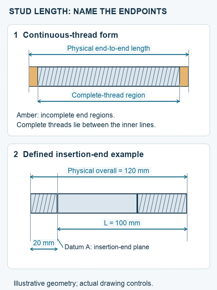
- Identify the form. Mark whether each end is intended for a nut, a tapped hole or another specified connection. Identify any central plain section and end features.
- Choose the two planes. Mark them on a copy of the drawing or an annotated sketch. If the order says overall length, use the physical ends. If it specifies another convention, reproduce that definition rather than relabelling an end-to-end reading.
- Take the reading with a suitable method. Use equipment with the range, resolution and access required by the agreed tolerance. A tape can help identify a long replacement part; it does not automatically establish compliance with a close drawing tolerance. Record burrs, damaged ends or uneven faces that prevent a repeatable reading.
- Record the result with its reference. Include units, drawing revision, measured feature and inspection stage. For an acceptance decision, use the specified tolerance and inspection procedure.
A removed service part can help identify an unknown item. Corrosion, deformation, damaged threads or previous rework can make it a poor dimensional master. Submit the original drawing when available; otherwise identify the sample measurements as replacement-identification information for review.
Example: 100 mm nominal is not necessarily 100 mm overall
Consider an illustrative custom stud whose drawing explicitly defines L from the insertion-end reference plane to the opposite physical end. The drawing also defines bm from that same plane to the insertion-end tip.
If L is 100 mm and bm is 20 mm, its physical overall length is 120 mm. A supplier quoting a 100 mm end-to-end part has interpreted a different dimension. This addition follows the chosen reference planes; it is not a universal stud-sizing formula.
The double-end stud product guide already uses an illustrative reference in which L excludes the insertion end. Keep the actual drawing in control. For a different form or standard, confirm its definition instead of carrying those symbols across unchanged.
At this point, record the two end threads separately: system, nominal diameter, pitch or TPI, tolerance class and required threaded length. If the ends differ, label them A and B. For thread-class interpretation, use the metric and Unified thread-class guide; matching diameter and pitch alone does not resolve a UNJ/UN mating question.
Check the usable region as well as the stud length
A correct overall length can still leave the nut in the wrong place. The chamfered lead-in, complete thread and any incomplete thread runout do different jobs. Specify the axial region that must provide complete threads, and review where the actual nut will sit within it.
For a double-end part, locate each complete-thread region from a named end or drawing plane. A single total threaded length can hide a short usable region on one end. Include the nut arrangement, washer stack and relevant joint thickness when reviewing whether the dimensions allow the required engagement.
NASA-STD-5020B discusses complete engagement and interference with incomplete runout threads in its spaceflight fastening guidance. Those geometric concerns are useful here, but its application-specific engagement and protrusion requirements are not universal industrial acceptance limits. [2, sections 4.7.4–4.7.5] The companion grip length and thread-length guide illustrates why the visible threaded region is not the whole answer.
For special alloys, measure the ordered condition
“A-286 stud, same dimensions as sample” leaves two decisions open: the required material/fastener condition and the stage at which dimensions will be accepted. Carpenter reports dimensional contraction during A-286 aging. [3, p.4] When heat treatment follows a dimensional operation, establish the final inspection stage rather than treating an earlier measurement as the finished result.
That observation is not a machining allowance to apply to every A-286 part. Inconel 718 needs its own specified material and finished-part route; an A-286 size-change figure cannot be transferred to it. Use the existing A-286 condition guide or Inconel 718 specification guide for the separate material and order requirements.
If a coating or other surface treatment is specified, state whether thread acceptance applies before or after that process. A material certificate does not replace a dimensional report. Likewise, a satisfactory thread-gauge result does not by itself report overall length, insertion-end length or every drawing dimension.
Carry one measurement definition from quotation to receipt
For the illustrative 120 mm stud above, a useful line in the enquiry is: “Drawing D-101 Rev A; physical overall length 120 mm; L = 100 mm excluding the 20 mm insertion end, measured from datum A; two end threads and their complete-thread limits as shown.” This is a geometry example, not a complete material specification or a recommended production tolerance.
| Order field | Information to keep together |
|---|---|
| Identity | Stud form, drawing number/revision, units and quantity. |
| Length | The stated length, both reference planes, physical overall length where different, and tolerances. |
| Each end | Complete thread designation, end features, thread extent and insertion/nut-side identity. |
| Material and condition | Specified alloy, applicable procurement/fastener requirements and final condition. |
| Verification | Final inspection stage, dimensions to report, sampling/acceptance requirements and lot traceability. |
At receipt, compare the result with the same definition accepted on the order. If a measured overall length differs from a purchase description, first check whether the endpoints match before deciding that the part is short. A genuine drawing deviation still needs disposition; it should not be resolved by silently changing the measurement convention.
Start with the continuous-thread stud/rod form, double-end stud form or stud, nut and washer set that matches the enquiry. Specify mating hardware separately; the stud alloy does not automatically select the nut or washer alloy.
Send BYBOLT the drawing or marked sketch, alloy requirement and quantity. Written requirements are also enough to start a review. The custom-fastener RFQ checklist covers the remaining purchase and evidence fields.