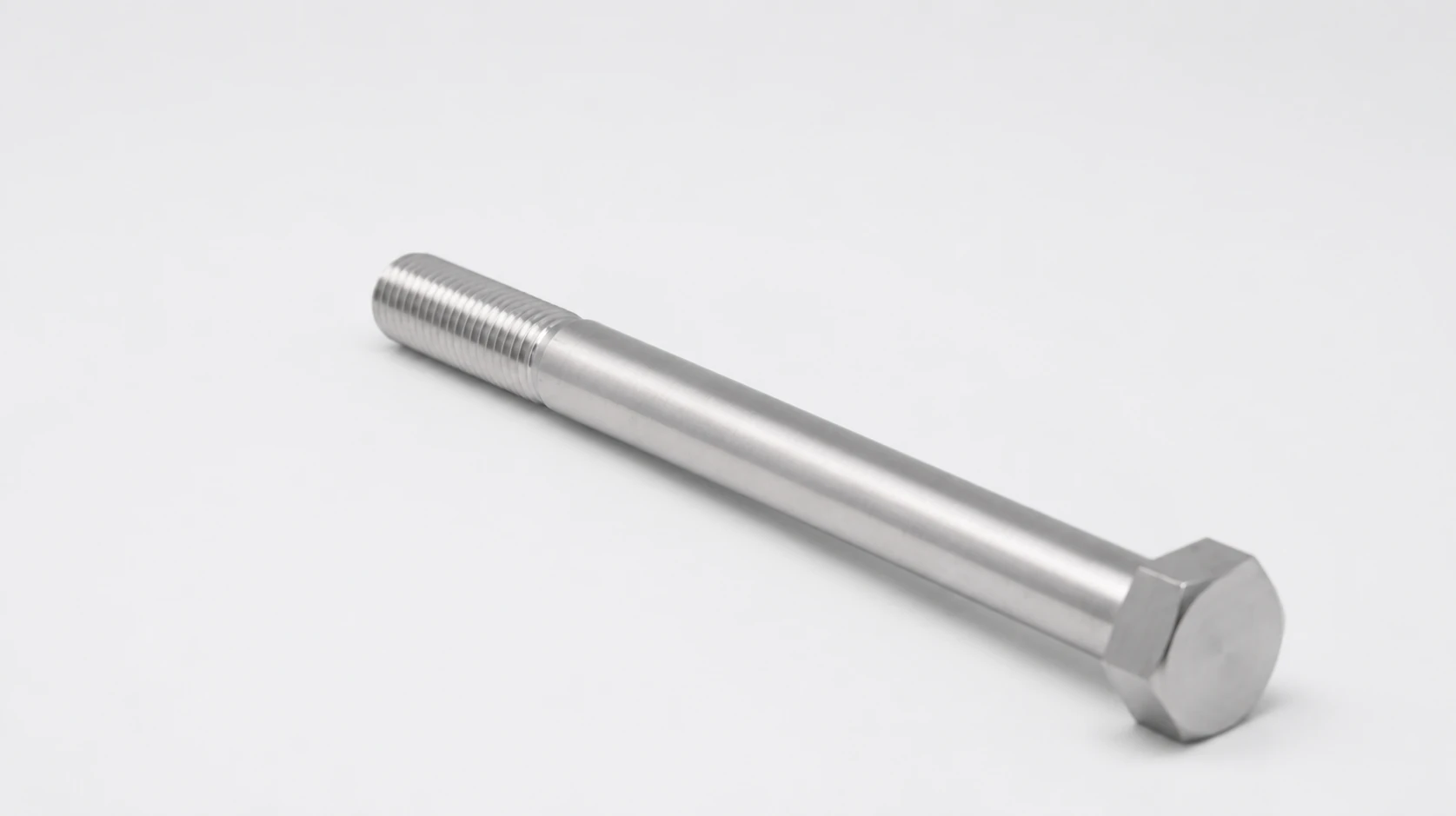
Bolt grip length and thread length describe different features, and “grip” itself needs a context. On a part drawing it may describe the plain shank; in a joint discussion it may describe the thickness being clamped. Identify that meaning before comparing it with the threaded portion. Also distinguish complete threads from the end lead-in and incomplete runout.
For special-alloy fasteners, a familiar diameter and an Inconel 718 or A-286 label do not settle those dimensions. A replacement bolt can have the expected overall length and still stop its nut before the joint is clamped. The order must locate the shank, complete threads and actual mating parts together.
This is the bolt-length branch of Threads and Dimensions for Special-Alloy Fastener Orders. For headless parts and insertion-end references, use the stud length measurement guide.
Separate the part dimension from the joint dimension
| Term or dimension | What it describes | What the order needs |
|---|---|---|
| Plain-shank length | The unthreaded portion of the bolt, using specified boundaries. | A labelled start and end; identify the adjacent fillet and thread transition separately. |
| Assembly grip / clamped thickness | The distance through the stack between the relevant bearing surfaces in that assembly. | The included plates, washers, spacers and their installed arrangement. |
| Thread length | A specified axial extent of threading on the part. | The definition used by the drawing or applicable product standard; do not substitute the visible threaded extent. |
| Effective length for a stiffness calculation | A model-specific representation of the loaded fastener. | The calculation method and its assumptions, rather than a new shop-floor synonym for shank length. |
NASA's Fastener Design Manual discusses joint stiffness, fastener stretch and material effects in design. [1] A calculation's effective length should therefore stay with that calculation. It does not replace a dimensioned part drawing, and a longer plain shank alone does not establish retained preload.
Mark the complete-thread region, not just the visible thread
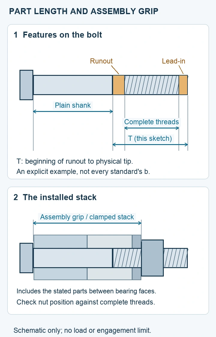
In the schematic, the example thread length T runs from the beginning of the runout to the physical tip. Its complete-thread length occupies only the inner region, excluding both amber zones. T defines the endpoints for this example; it is not the definition of b in every product standard. Use the controlling drawing or standard to interpret the thread-length dimension on an actual order.
The runout is the transition where the thread becomes incomplete towards the plain shank. At the opposite end, a chamfer or lead-in also reduces the fully formed thread region. Between those limits lies the complete-thread region available for the specified mating engagement.
A drawing may use a thread-length dimension with a particular standard definition. If the joint needs complete threads at a specific position, locate that region explicitly rather than assuming the thread-length label alone guarantees it. Identify the end reference, tolerance, runout/relief requirement and any controlled unthreaded length.
NASA-STD-5020B addresses full engagement and interference with incomplete runout threads for spaceflight fastening systems. [2, sections 4.7.4–4.7.5 and Figure 2] The mechanism is relevant to understanding the sketch. Its installation requirements do not become a universal number of protruding threads for industrial Inconel 718 or A-286 bolts.
If the nut stops early, compare its seated position with the thread region
Begin with the geometry rather than adding tightening force. Place the actual nut, washers and clamped components on the same drawing as the bolt. Locate the nut's intended bearing face relative to the complete-thread boundaries.
- Can the nut reach that face without its internal thread running onto the bolt's incomplete runout or plain shank?
- Does the intended seated position leave the required engagement within the available complete threads?
- Do the diameter, pitch/TPI, thread form and tolerance class match the mating part?
- Are the end condition, surface treatment and any damaged or contaminated threads relevant to the stoppage?
These checks identify information for review; they do not diagnose every stuck nut. Do not force a tight assembly or prescribe extra washers as a universal correction. A washer changes the stack and bearing position; accepting that change requires the responsible design or assembly review. The thread-class guide and UNJ/UN compatibility guide cover separate fit questions.
What changes for a special-alloy purchase?
The measurement definitions do not change simply because the alloy changes. The purchase review does need to keep geometry, material condition and final inspection connected.
For an A-286 part, define the inspection stage. Carpenter reports dimensional contraction during aging. [3, p.4] If the manufacturing sequence includes heat treatment after a dimensional operation, confirm which finished condition the length and thread acceptance refer to. This is not a general machining allowance.
For an Inconel 718 replacement, preserve the full requirement. Copying the old part's length does not establish its material condition or finished-fastener performance. Carry the drawing revision and governing specifications with the dimensional record; use the Inconel 718 order guide for that separate review.
For a high-temperature joint, keep the assembly context. Service temperature, mating materials and the installed stack belong in the review when they affect selection. This page defines the cold part and assembly references; the high-temperature preload guide explains why dimensions alone do not predict retained load.
Where a coating or surface treatment is required, state the thread acceptance stage and any specified condition for assembly. Material certification and sampled GO / NO-GO gauging do not, by themselves, document every axial length or the completed joint's behaviour.
Write the lengths so two suppliers quote the same part
Instead of “long grip bolt, part threaded,” send a marked sketch that identifies the bearing surface, tip, plain shank, complete-thread region and transition. State the dimensional standard and edition when one controls the product. ASME B18.2.1 covers specified inch-series bolt and screw forms; its public scope does not provide every drawing value or make different forms interchangeable. [4]
| RFQ item | Useful description |
|---|---|
| Part length | Length between named reference surfaces, units and tolerance; identify the head form. |
| Shank and thread | Plain-shank extent, complete thread designation and required complete-thread boundaries; define runout/relief where controlled. |
| Assembly | Required bearing position, clamped stack and mating nut/washer or tapped-hole details. |
| Alloy and condition | Material and finished-part requirements, heat-treatment/delivery condition, specified surface treatment. |
| Acceptance | Drawing revision, final inspection stage, dimensions to report, sampling and required documents. |
For example, an enquiry can say: “Length from bearing face A to end B; complete-thread region between planes C and D; nut seating plane E shown in the assembly; dimensions and tolerances to drawing Rev B.” Fill in the actual values and specifications. The labelled planes make this more useful than a single undefined grip length, even before the alloy and quantity are added.
Use the long-shank hex-head bolt or hex-head bolt form that matches the enquiry. Those product pages retain their dimension previews and purchase details. For a special-alloy order, state the alloy explicitly rather than treating the product silhouette as a material selection.
Send the drawing, alloy requirement and quantity to BYBOLT. If the drawing is incomplete, a marked sketch or written requirement can start the review. Use the RFQ checklist to complete the remaining purchase scope.