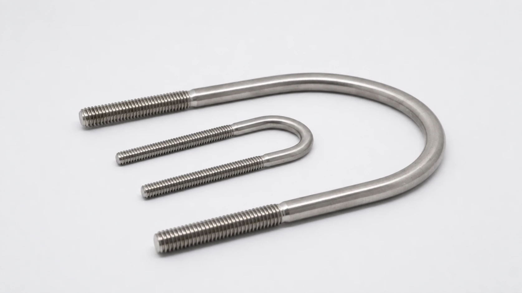
Two U-bolt quotations can both say “100 mm wide” and describe different parts. One supplier may mean the clear space between the legs; another may mean the distance between their centres. The difference affects the fit before material or price is considered.
Specify a U-bolt with labelled datums (measurement references): inside width, leg-centre distance or outside width; inside or overall height; bend profile; and usable thread on each leg. Include the rod diameter and complete thread designation. A marked sketch is more useful than an unqualified width × height description.
Inside width and leg-centre distance are different dimensions
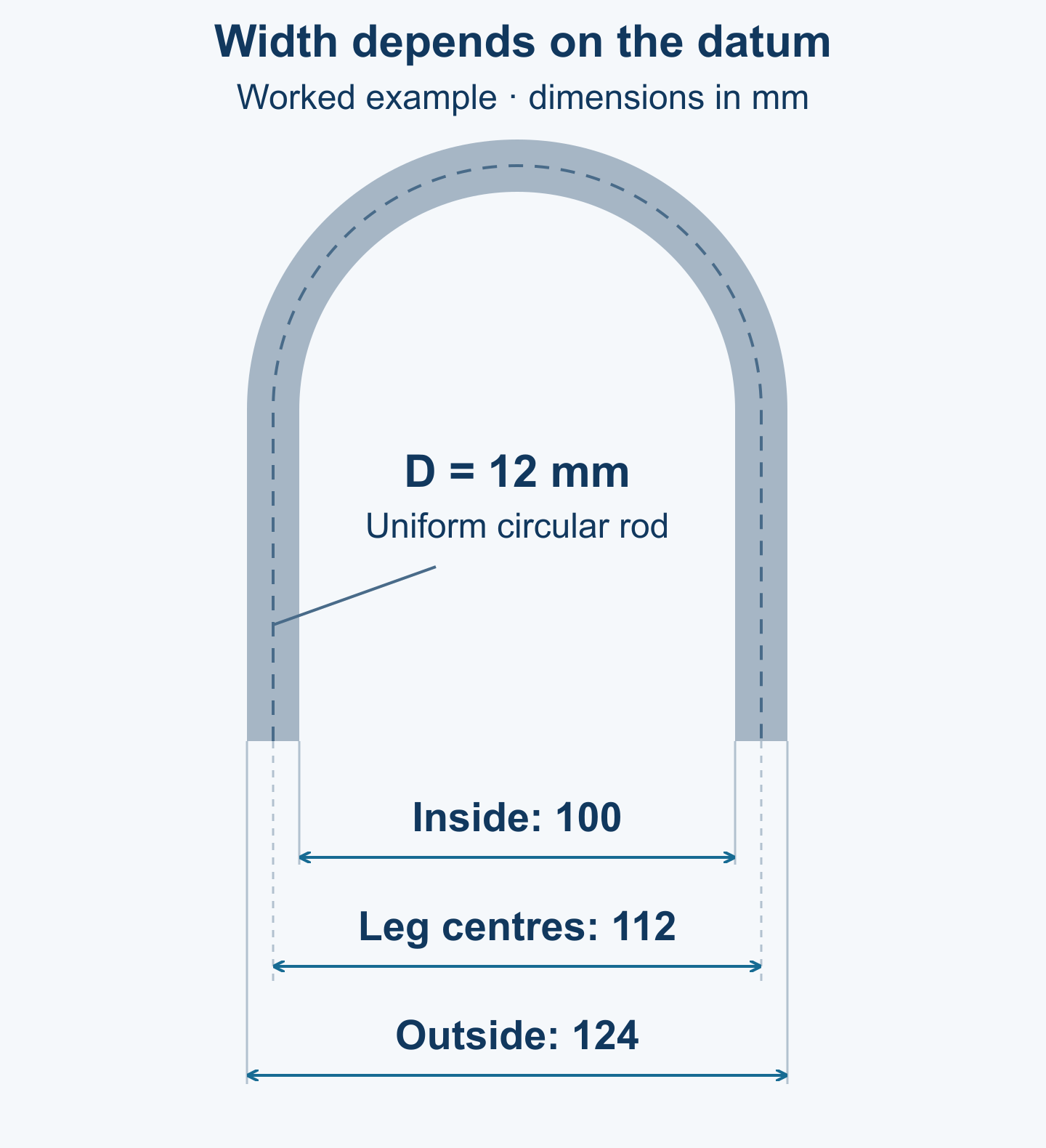
For straight, parallel legs made from uniform circular rod, the three width measurements are related by simple geometry. Let D be the actual rod diameter at the measured section. The centre of each leg is D/2 from its inside surface, so:
- Leg-centre distance = inside width + D.
- Outside width = inside width + 2D.
In a worked example with D = 12 mm and an inside width of 100 mm, the leg centres are 112 mm apart and the outside width is 124 mm. These are example dimensions, not a standard size or an offered production range.
Now consider a quotation that uses 100 mm as the centre distance with the same 12 mm rod. Its inside clearance would be 88 mm. It does not describe the same geometry as the 100 mm inside-width example. Resolve the datum in writing rather than treating the two width labels as equivalent.
The relations above do not cover tapered, nonparallel or noncircular legs. Nor should D be filled in from the nominal thread callout without checking the body geometry. For a plate with two holes, provide the hole-centre distance, hole dimensions and their tolerances as well as the U-bolt drawing.
Define height from the crown to a named end plane
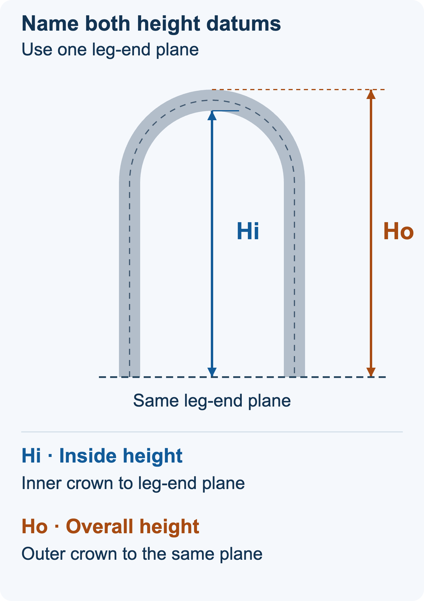
“Height” needs two endpoints. Measure height along the leg direction. An inside-height measurement starts at the inner surface at the top of the bend (the inner crown); an overall-height measurement starts at the outer surface there (the outer crown). Both must finish at the same specified leg-end plane if they are to be compared. If the legs end at different levels, dimension each one rather than hiding the difference in a single overall height.
Show whether the bend is round, square or another controlled profile. Identify an inside radius or a centreline radius explicitly. A width measurement does not define every possible bend shape, and the radius of a round-bend part cannot simply be transferred to a square-bend drawing.
ASME B18.31.5-2011 (R2021) addresses bent bolts in the inch series, with different dimensional coverage for different configurations. Its public description also provides for identifying dimensions, material and finish for configurations outside its dimensional tables. A standard number therefore still needs the applicable form and ordering details. [1]
Check usable thread against the nut and plate arrangement
A long threaded-looking region does not guarantee that a nut can reach its required seated position. Incomplete lead-in threads near the leg end and the runout—the transition from complete threads towards the unthreaded shank—are different from the complete thread region available to the nut.
On each leg, mark two axial boundaries: where complete threads begin after the end chamfer or lead-in, and where they end before the runout. Identify both positions from the same specified leg-end plane. Their separation defines the continuous complete-thread length; it is not the total visible threaded length. Show the plate or saddle, washers and the seated nut on the same sketch, so the nut’s required engagement can be checked against that region. Agree the controlling definition and tolerances on the drawing; a single undefined “thread length” does not locate this region or resolve the fit.
NASA-STD-5020B discusses full thread engagement and interference with incomplete runout threads in its spaceflight fastening-system guidance. That guidance helps explain the geometric issue; it is not a universal installation rule for every industrial U-bolt. Use the drawing and applicable project requirements to define engagement and any required protrusion. [2, sections 4.7.4–4.7.5]
Include the actual nut style and washer arrangement in the review. A different nut height, saddle thickness or washer stack can move the required seated position even when the U-bolt's overall dimensions are unchanged. Do not use a visible thread count as a substitute for checking that geometry.
Keep the material condition and final dimensions together
Dimensions establish fit; they do not establish a load capacity or tightening torque. The material grade, final condition, bend requirements and complete connection still need their own review. Reproducing a removed part's shape alone does not establish its original tolerance or service capability.
Where treatment follows forming or machining, identify when the final dimensions will be checked. For example, Carpenter reports dimensional contraction during A-286 aging. That is a reason to agree the final inspection stage, not a general bend allowance for a U-bolt. [3, p.4] The A-286 heat-treatment guide explains the separate condition and process questions.
Turn the measurements into one unambiguous enquiry
Start from the U-bolt product page and send a drawing or marked sketch with units, the width and height datums, rod and thread details, bend profile and quantity. Include the mating parts and material or service requirements already known. If a dimension or condition is unresolved, identify it for review; a complete production drawing is not required to begin an enquiry.
For quotation comparisons, keep the accepted geometry and included hardware together. The custom fastener RFQ guide helps carry those requirements into the purchase scope. BYBOLT deliveries include an MTC / EN 10204 3.1 certificate, heat-number traceability and mechanical testing; threaded products include sampled GO / NO-GO gauging. Test objects, methods, sampling and acceptance follow the agreed order. PMI, third-party inspection and additional records are agreed separately.